Adding a PCIe to a Dell Wyse 5070
Investigating the feasibility of adding a HBA card to a thin client.
The project is based on KCORES-5070 reverse engineering.
Why the Dell Wyse 5070?
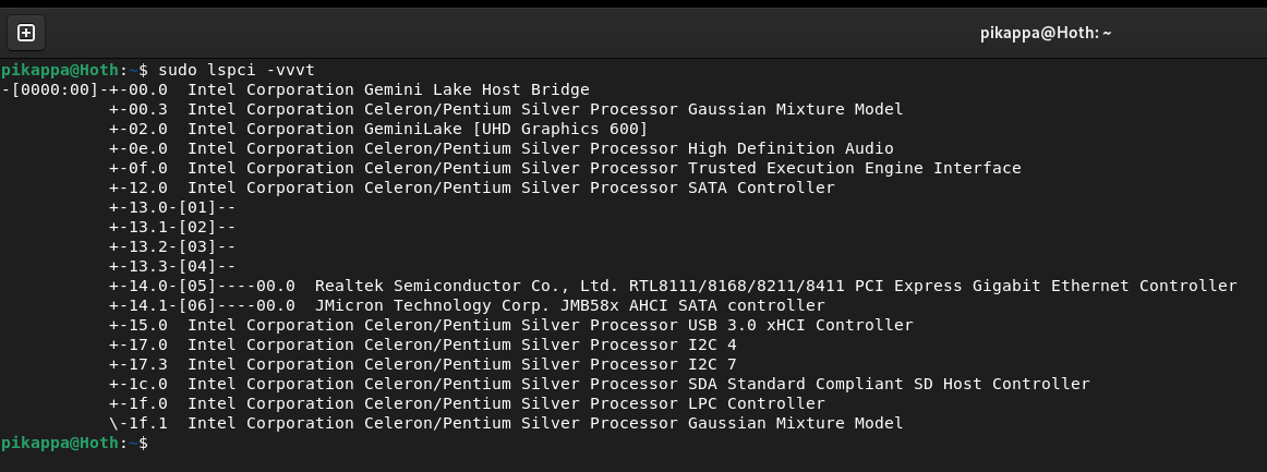
Having outgrown my twin raspberry 3b+ setup, I needed something bigger, faster, with more ram and above all else, easily and cheaply expandable. And here comes this little wonder, with 4x 2.5 GHz cores at 100% using 10W of electricity, measured at the wall. I dare to say it’s more energy efficient than Raspberry Pis. It also shares the same motherboard with its bigger brother - Wyse 5070 Extended, which supposedly allowed adding PCI express port.
I’ve read the KCORES docs, they wrote that adding the slot is possible, provided schematics for missing clock request components, and the biggest hurdle they mentioned was cleaning lead-free solder from unpopulated PCIe mount point. That can’t be that hard, right?
The desoldering.
Yes, it was hard at the beginning. I’ve never done that on scale before. Also the board is 1.6mm thick while the holes are like 0.5mm wide. Half of them are connected either to ground planes or power planes, and those suck heat and freeze solder right away. I’ve tried the following:
- wicking the solder clean, it doesn’t work, frozen solder can’t be wicked, frozen solder in the middle of pcb, hugging ground plane can’t be easily melted.
- using sucker pump, the same, solder has to be liquid
- stainless pins that you insert into liquid solder, let it freeze and pull out, leaving a nice opening. Same as above.
- adding leaded solder, this actually helps, but not enough on its own, perhaps low melt solder would do.
It is possible to desolder using mix of techniques above, but there will be damage like exposed traces, solder mask gone, ripped pads etc. The gamechanger was using my ender 3 as makeshift heat plate. Print bed heated to 110C, leaded solder added and suddenly a 5$ sucker pump was doing a perfect job.
Ofcourse if you own a hot gun, the whole ordeal can be skipped, as you can heat up the whole slot and insert the connector. The leaded solder still helps. And be sure to bend the 12v pins so they stay floating, ready to be connected to a proper 12v rail if you choose so.
Adding the PCIe connector.
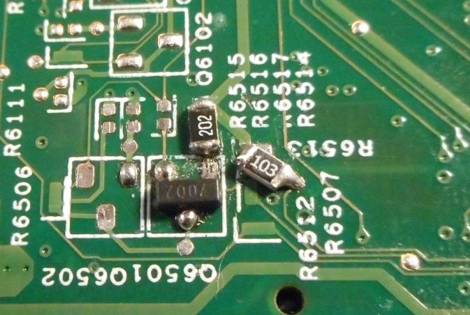
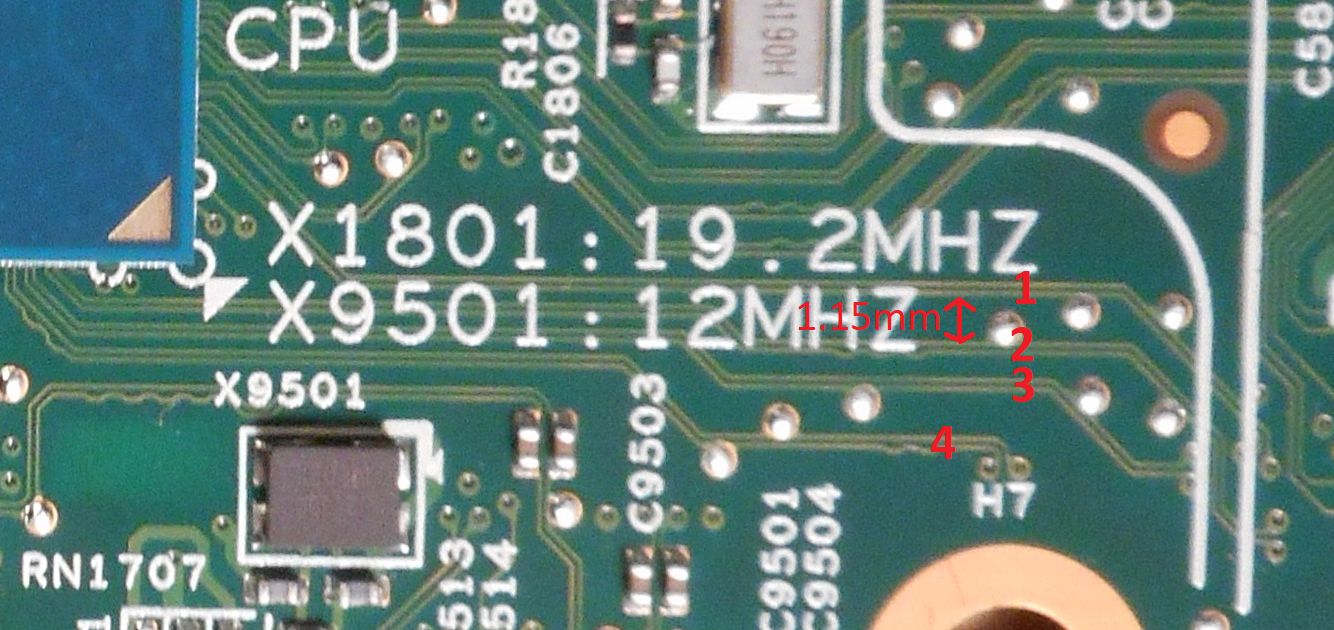
On the back of the board, clock request circuit is missing and needs to be added. If you don’t like hand-soldering 0402 components, bigger ones can be used too.
Warning: The Wyse 5070 does not provide 12 V on the PCIe power pins. These pins are connected directly to the 19.5 V input.
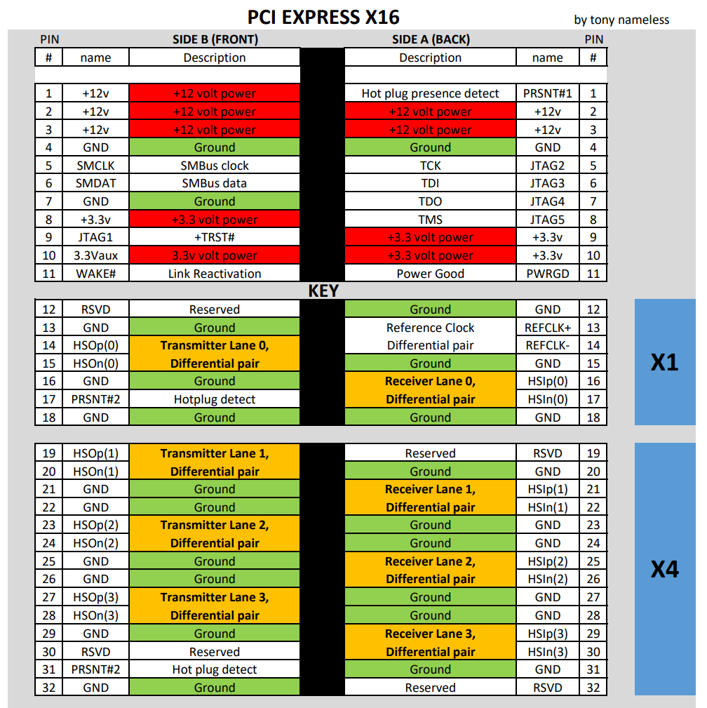
This can be dealt with in few ways:
- Many PCIe cards do not need 12v rail, if your card is one of them, simply do not solder those pins, put solder mask or nail polish on them for safety. Cards tested and working on 3.3v only: 1Gbps RTL8111E NIC aliexpress brand, 2.5Gbps RTL8125 NIC aliexpress brand, two different PCIe -> m2 nvme adapters, aliexpress brand, Adaptec ASC-1405 HBA
- It is possible to power up Wyse 5070 with 12v psu but I have not tested it. There will be issues with unoriginal psu, which disables turbo mode, but supposedly can be overridden with modded BIOS or runtime changes. I’ve tried modified BIOS provided by KCORES, but being an older version than my current, the machine didn’t even boot up.
- A buck converter can be used to step down to 12v or a secondary psu with 12v rail, provided the ground is shared.
What the KCORES failed to communicate clearly
This, by far, was the biggest obstacle during the research. I had done everything that other people did when adding the port, all my PCIe x1 cards worked, but all x4 and wider cards did not. That led me down the wrong path of investigating the link width. Only after reviewing all files provided by KCORES I realized that there are no coupling capacitors on TX lines. Many ‘simple’ PCIe cards work without them, this includes 1Gbps and 2.5Gbps realtek NICs, PCIe-to-nvme adapters, but more sophisticated cards like Adaptec asc-1405, LSI 2308 won’t work.
According to the PCI Express Base Specification Revision 2.0 PCIe:
All Transmitters shall be AC coupled. The AC coupling is required either within the media or within the transmitting component itself. Min 75nF, max 200nF for both 2.5 GT/s and 5 GT/s. 1
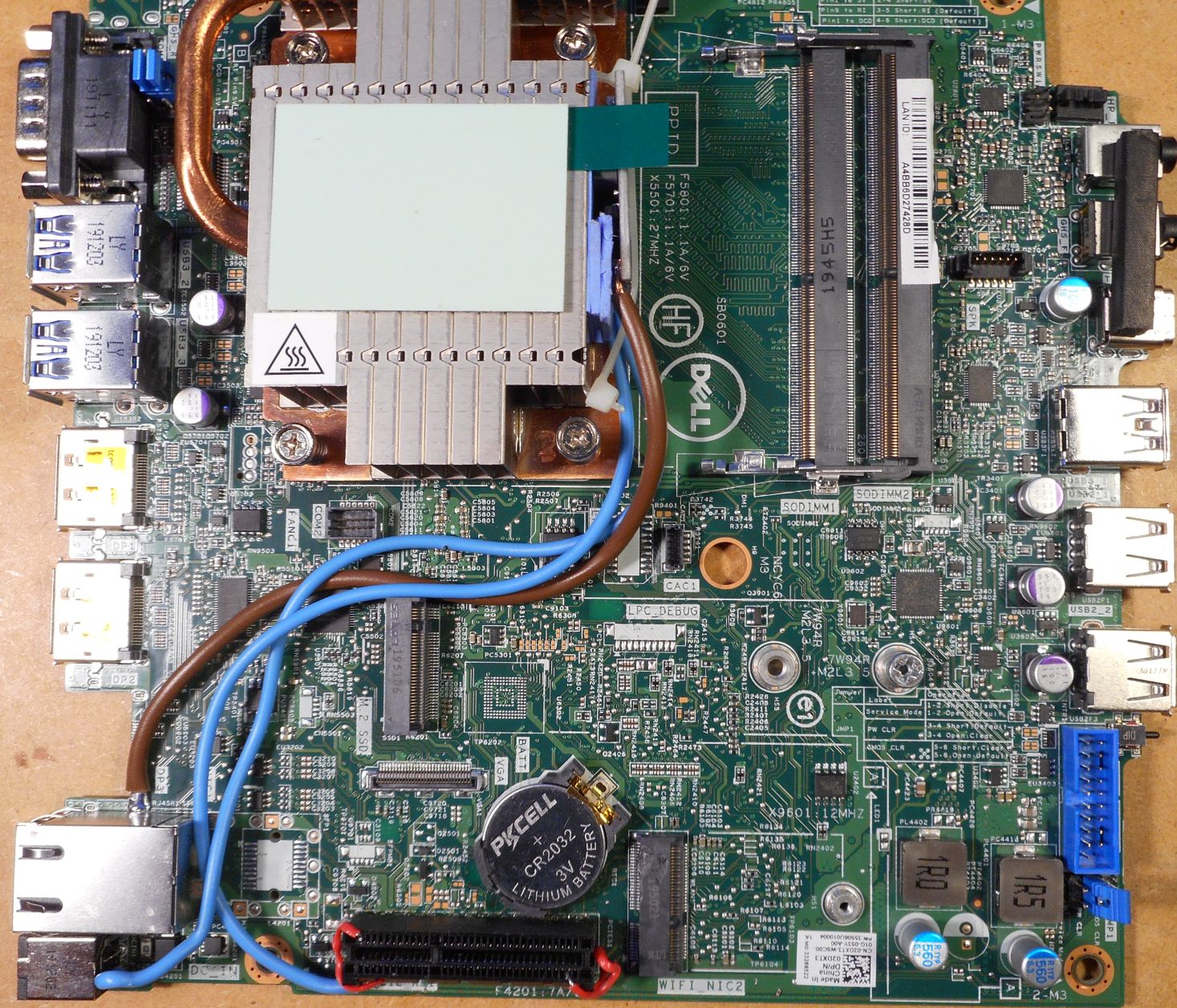
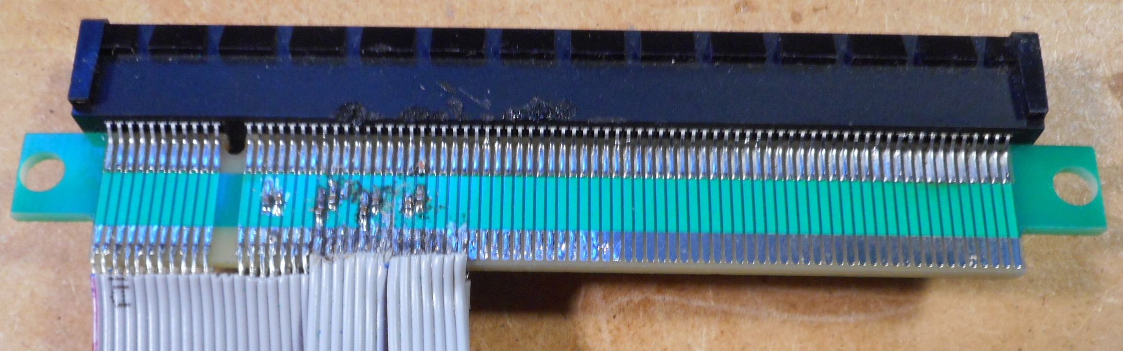
The Wyse 5070 motherboard does not have them on these lanes. The Extended version instead has the capacitors installed on the PCIe riser. The PCIe lanes are accessible on the pcb only near the cpu, then quickly disappear into internal pcb layers and surface right to the PCIe connector. Maybe someone with good microsoldering skills could put them near cpu, but realistically putting them on riser is the only option. Tests have proven that putting those capacitors at the very end of TX (which is contrary to the spec) still works and both Adaptec and LSI HBAs link at max possible speed.
Another thing is, the power comes directly from the psu, therefore it is always on, irrelevant of machine state. For always-on device, it’s not of a big issue, but you may consider adding a simple circuit based on P channel mosfet slaved to 3.3v rail for power control.
Disassembly hazards.
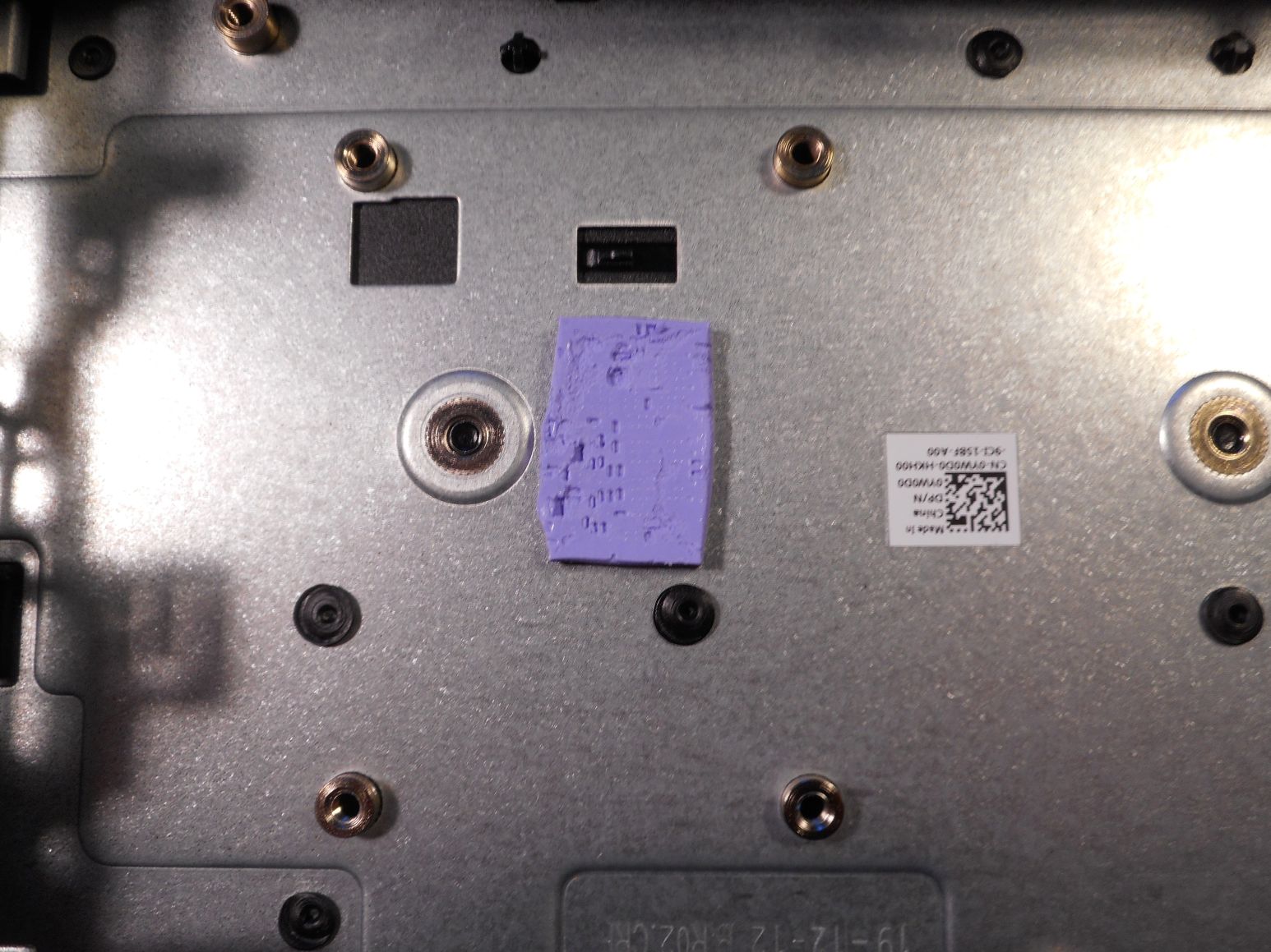
There are reports of people damaging the motherboard during disassembly. Getting the board to work on for the first time can be a bit tricky, the board is a tight fit in the case, it cannot be simply lifted up and out, it has to be carefully slipped out at least half its length before it can be removed. There are components on the back that will clip on the screw mounts while sliding, so it has to be done slowly and carefully. Even worse, the CPU heatsink is thermally coupled with the case itself (sure it helps with heat management, but check this out), the upper thermal pad has a plastic film so it slides against the removable side, that’s easy. The lower pad is glued to the back (bottom?) of the case, and the CPU support components on the back are pressed into it (see the photo) and stuck in it like in mud, which prevent sliding of the motherboard to the side. You need to lift the edge (that would be the right side in the photo) about 2mm, the pcb will slightly bend and tension will slowly separate it from the pad.
This concludes the “adding ONE PCI express port to wyse 5070” project, but the research is still ongoing.